SYNLESS KEYPAD
Custom mechanical keypad
(2016 - 2022)
1. PRESENTATION
Long time PC player, I play with a very low mouse sensitivity. Because I kept bumping my mouse into my keyboard I was craving for more room on my desk. I decided to create my own mechanical keyboard and move my regular one elsewhere, and also add some features in the process. Here is the list of requirements :
2. DESIGNING THE PCB
The first step is to create a PCB. I went with Eagle CAD and created a two layer PCB of about 135mm x 120mm. The hardest steps here are finding the correct parts to use (or to create them entirely) and not making any mistake during routing.
a. THE SWITCHES
I wanted this board to be compatible with Cherry MX style switches and to be hot-swapable. Here I used footprint for Kailh hotswap sockets
The keys are arranged in a matrix configuration, with 5 lines and 7 columns.
b. THE MICROCONTROLLER
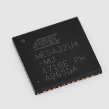
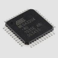
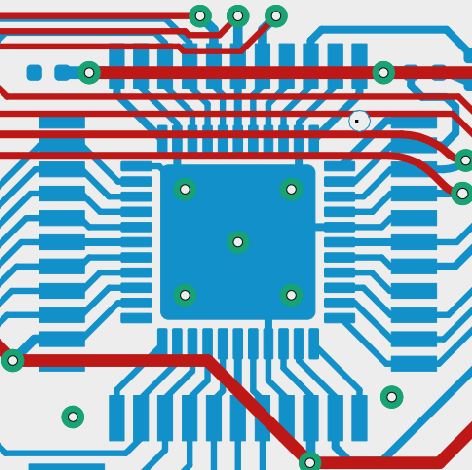
Here I went with the most common microcontroller I could find : the Atmega 32U4. This microcontroller is at the top of the supported list of MCU for both QMK and Arduino. It is available in multiple packaging and has a wide availability. I used the QFN variant at first (in 2017), but the price kept increasing and the availability started to be problematic. Since then I switched to the TQFP variant. This was possible because I have both footprints in my design :


c. THE PCB & SCHEMATIC
I quickly realized that to fulfil all my requirement, a single MCU would not be enough. QMK has no support for Xinput and Arduino is not as seamless as QMK (incompatible with some BIOS for ex.). So I've decided to use 2 MCUs on a single board. One will take care of the regular keys (QMK) and the other one will handle the joystick (Arduino Xinput). The QMK MCU is the master and drives the Arduino MCU using 3 shared pins. I also implemented a USB HUB on the PCB so only one USB port is needed :
With this board I can generate the Gerber files to be processed by a manufacturer. I choose JLCPCB since they are also able to solder all the SMD components (and they charge no extra for various options including soldermask color). Soldering on my own about a hundred SMD components per board with a 0402 package is a no-go. I added holes for M2.5 standoffs, to mount a case later on.
3. THE BOARD
A few weeks later the boards arrive (batch of 10). The mate black soldermask is looking good and there is no manufacturing defect.
I could burn the Caterina bootloader without any problem using an Atmel ICE programmer. I added the joystick right away to make sure that this critical part was working as intended. And it did. Both when mounted on the right side and on the left side. The 2 MCUs and the USB HUB are detected correctly by Windows :

Then comes the assembly :
I've designed the case using Soldworks 2016. It was then printed on a Creality CR10 3D printer using PLA plastic. There is a bottom part, held against the PCB with screws, and a top part, help against the PCB via the 30 switches.
The switches used are either C³ Tangerines switches (the smoothest there is) or Gateron Oil King switches (my personnal favorites). For keycaps, I use a set of blank PBT with DCS profile at the moment
4. PROGRAMMING AND LAYOUT
First off, I had to setup QMK MSYS, then create a new board with my desired configuration, and I was just a make synless:default away for my goal!
Here is the default layout :
const const uint16_t PROGMEM keymaps[][MATRIX_ROWS][MATRIX_COLS] =
{
[0] = LAYOUT_default(
KC_ESC , KC_1 , KC_2 , KC_3 , KC_4 , KC_5 , KC_6,
KC_TAB , KC_Q , KC_W , KC_E , KC_R , KC_T , KC_Y,
KC_TAB , KC_A , KC_S , KC_D , KC_F , KC_G , KC_H,
_______, KC_LSFT , KC_Z , KC_X , KC_C , KC_V , _______,
_______, KC_LCTL , KC_LWIN , KC_LOPT , KC_SPC, _______ , _______
)
};
Here is a more visual representation of it :

By default the joystick is affected to the arrow keys. When the joystick is moved pass the dead-zone threshold, it will register and unregister one of the arrow key. When pressing 6 and space together, the QMK MCU stops reporting the joystick state and order the Arduino MCU to report the joystick state as an Xinput joystick. To let the user know that the joystick mode has changed, the rumble motor is briefly activated
When compiling the code for a joystick on the left side, only a single boolean needs to be changed.
5. CONCLUSION
During this project I have utilized my electronics and programming skills and enhanced my gaming experience. I now have more ease using 32bits Atmel chip and routing larger boards. I've used this keypad extensivly over the past years and the different revisions have only improved it. The joystick is surprisingly comfortable and very useful in all types of games, especially as a ping wheel.
I am pretty much done with this project until I find a lot more time to try analog switches on a new revision of this board
When I was in the USA for work, I order a case from Sendcutsend.com (laser cutting service). The result is a rather exotic sandwich of steel, aluminium and plastic. With some relegendable keycaps it makes for a very catchy hardware piece on my desk :