SYNLIGHT
Homemade Ambiligth system for Windows
1. PRESENTATION
The idea behind this project was to create my own Ambilight system. Such system uses LEDs on the rear of the screen to replicate the color of its edges. This creates a pleasant experience while watching movies but is also enjoyable on a daily use, as it reduces visual fatigue. I love this feature but unfortunately it is only available with Philips TVs. I spent some time playing around with individually addressable RGB LEDs (WS2812B, also known as Neopixel from Adafruit) and I program softwares to run on Windows regularly so why not try to combine these two ?
In addition, I could add several features among which :
HOW :
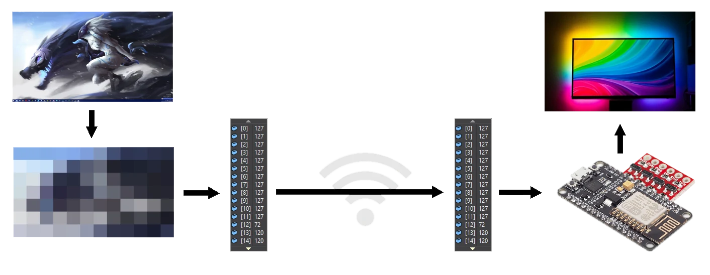
In order to change the LEDs color according to the outside pixels from my monitor, I have to take screenshots, to process them, to send the informations to a microcontroller (NodeMCU ESP8266 at first, ESP32 later) and have it drive every LED accordingly.
DISCLAIMER AND LIMITS :
My solution is a software that runs on a Windows computer. It is not an physical solution with video input and LEDs as output. I've seen such solution on the Internet and even tried some. For many reasons hardware these solutions don't please me and I keep my setup as presented below. I tried to use DirectX direct capture with SmallDX but it didn't improve the maximum frequency of the process nor allowed me to capture in-game screenshots (corrected down the road). As my programing knowledge is limited when approaching GPU access and since the performance is good enought, I am sticking to CPU computing. The CPU load is light enough to let it runs in background and forget about it on most computers.
2. PC PART
To program the PC software I went with C# .net and Microsoft Visual Community. I used the Model-View-Viewmodel architecture instead of the more simple Windows-form-application architecture as it was part of my learning. It is not a perfect MVVM implementation but it was enough at the time.
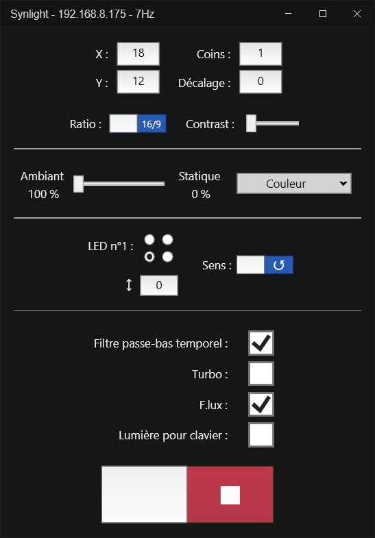
a. THE USER INTERFACE
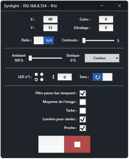
Here is a view of the user interface that bears the controls needed to match most setups.
Each of these value can be changed in real time while the program is running, and can also be set manually in the parameter file, and let the program run in background
b. CAPTURING A FRAME :
In order to capture a frame let's declare a simple Bitmap matching the size of the screen :
int screenWidth = (int)SystemParameters
.PrimaryScreenWidth;
int screenHeight = (int)SystemParameters
.PrimaryScreenHeight;
Bitmap bmpScreenshot = new
Bitmap(screenWidth,screenHeight);
Now lets fill this fresh Bitmap with the pixels of the screen using the Graphics object :
Graphics gfxScreenshot =
Graphics.FromImage(bmpScreenshot);
gfxScreenshot.CopyFromScreen(0, 0, 0, 0, Screen);
Almost done. Now a nice tips regarding the Bitmap constructor : it is possible to create a new Bitmap from another while changing its size. For a better understanding, take a look at the following line :
Bitmap bmpScreenshot = new Bitmap(bmpScreenshot, Width,Height);
Here is created a new Bitmap with the number of LEDs in the X axis as width and the number of LEDs in the Y axis as height, way simpler to process ! The freshly new Bitmap object will looks like a rather small 2-dimensional array of pixel.
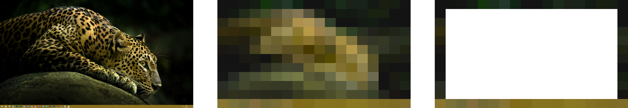
The three images above show the desktop screenshot, the resized one and finally the relevant parts of the resized screenshot : the edges.
c. SCANING :
Scanning the Pixels consists of adding to a byte array the R component (red), then the G component (green), then the B component (blue) of every pixel. This could be summed up by the following code :
byteToSend = new byte[600];
//UP TO 200 LEDs
byteToSend.Add(
scaledBmpScreenshot.GetPixel(x, y).R );
byteToSend.Add( scaledBmpScreenshot.GetPixel(x, y).G );
byteToSend.Add( scaledBmpScreenshot.GetPixel(x, y).B );
Straightforward. Each pixel fills 3 bytes of the byte array. The way the scaled Bitmap is scanned depends on the first LED position and on the direction of rotation.
Some tricks can be performed as well. For example, a software low-pass filter merges the current pixel array (byteToSend) and the previous one (lastBytToSend) to generate the array to be sent (newByteToSend). This prevents flickering and smooth out the color changes.
d. WIRELESS COMMUNICATION :
This system is targeting local networks. The PC software can find an NodeMCU on the network by sending a "ping" broadcast, expecting a "pong answer". At the end of every process loop, once the resized image has be scanned, the pixel array is ready to be sent. This is done by this line of code :
sock.SendTo(bytesToSend, endPoint);
Here, endpoint represents both the IP address of the NodeMCU and the port it is listening on.
3. NODEMCU PART
The NodeMCU is connected to the network using a hardcoded IP and regular Wifi credentials. Nothing to see here.
Once connected, the NodeMCU waits for incoming UDP packet. Upon receiving one that is not a special command, it affects the values to the corresponding LEDs :
if(UDP.parsePacket()>0)
{
UDP.read(packetBuffer, UDP_TX_PACKET_MAX_SIZE);
for(int n = 0; n<=packetSize -
3;n += 3)
{
red = packetBuffer[n];
green = packetBuffer[n+1];
green = packetBuffer[n+2];
strip.SetPixelColor( n/3,RgbColor(red,green,blue) );
}
strip.Show();
}
And voila ! When starting the PC program while the NodeMCU is connected to the local network, the LEDs start to shine within a second.
4. CONCLUSION
For a first project that is not just a compilation of scripts, it works very well. Communication over Wifi
works great and is significantly faster than Serial for this usecase.
UPDATE 05/04/2017 - Major performance improvement
Thanks to AloyseTech's suggestion, I was able to change the frame capturing method. I used to grab the whole screen (A) but now I strictly look at the useful parts (B) :
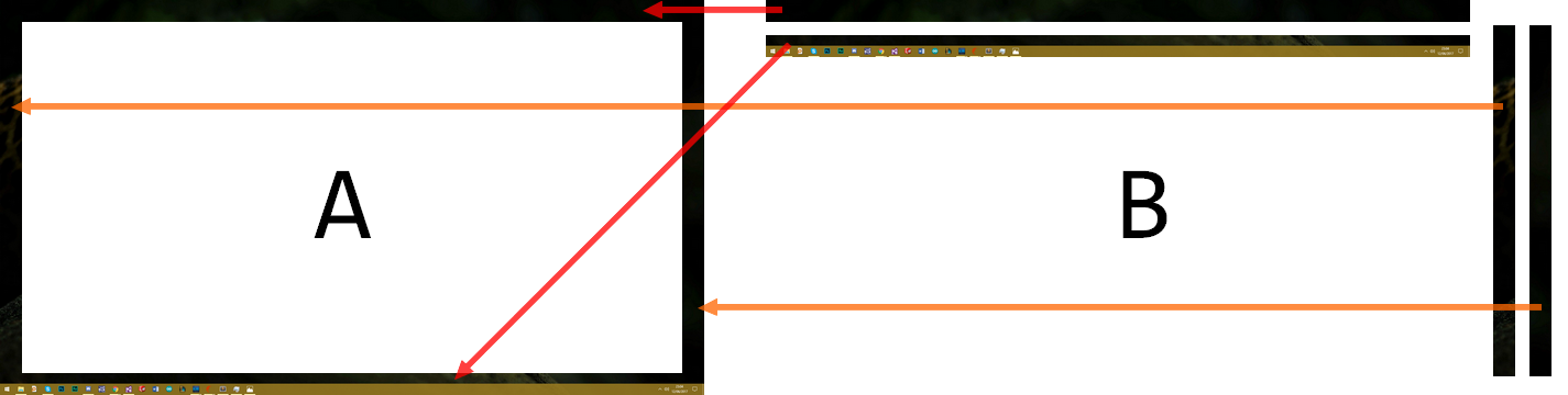
Even though 4 operations are needed, it is still faster due to the lower total size captured and the lower pixel count. This improvement allows for a decreased CPU usage and faster loop, meaning higher frequency. Later on, I made use of Tasks to grab each parts.
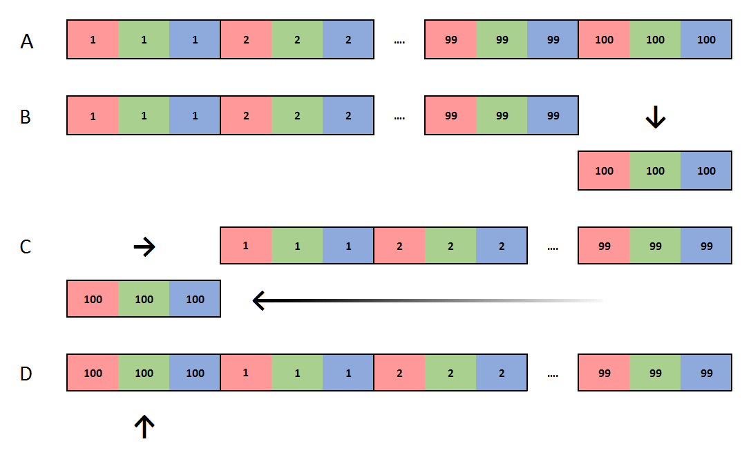
UPDATE 06/10/2017 - LED circular shifting
I received a request on GitHub to update the program in order to accommodate setups where the first LED is not in a corner. Each shifted LED makes a 3 bytes left or right circular shift of the array to be sent. Here is an illustration of a 3 bytes right shift of a 100 LEDs array :
UPDATE 09/11/2017 - Custom static color
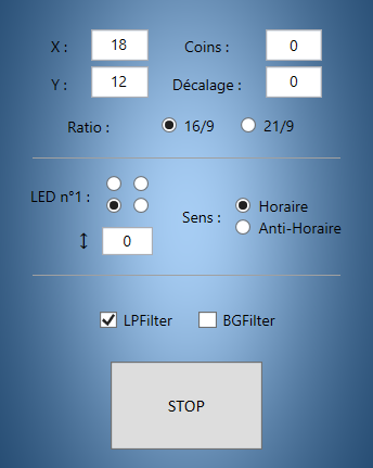
Not part of the original ambient lighting system, but nonetheless interesting to have : Static colors. Here is a view of the static color tab :
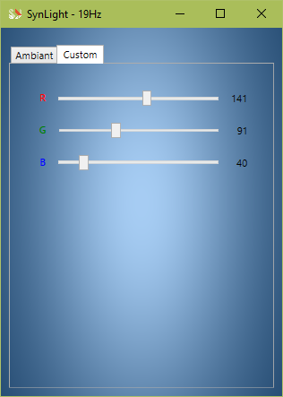
The color to be displayed by the LEDs is made from the 3 sliders representing red, green, and blue. I tried to implement a color picker, the same that be found in various photo editing softwares, but that will be for another time.
UPDATE 02/03/2018 - Multiple payloads and visual refresh
Sending UDP payloads to the NodeMCU is limited to arrays no longer than 1470 bytes. This was discovered after a question asked on GitHub. Both the C# program and the controller were updated to support multiple payloads, containing the colors of the LEDs, followed by a terminal payload, telling the NodeMCU to refresh the colors.
Here is an example corresponding to 1870 LEDs :

This is an example with the maximum size. Later I chose 1200 as the maximum payload size for every payload.
The program also got a visual refresh :
- "Style" and "Tempaltes" elements are applied on the controls
of the view
- Some checkboxes have been replaced by toggle switches
- The static color can blend
with the ambiant light and is integrated in a single tab, with a ColorPicker control instead of sliders
-
Custom topbar to remove the icon
UPDATE 28/07/2025 - Integrated into a WLED system
I made an board that integrates this project with WLED (with sound detection). Click on the image to see more

UPDATE 18/03/2026 - .net 10 migration
Updated to .net 10 + small visual refresh + code refactoring. The code runs a bit faster. When [Turbo] is enabled, it goes up to 100Hz.